|

Clutch and Flywheel Instructions and Information
|
WARNING!! Cast iron flywheels can be moderately lightened for STREET USE ONLY. Some excess can be safely removed, but the limit should be around 5 pounds. Auto manufacturers make their flywheels thick and heavy to overcompensate for the porosity and brittleness of cast iron material. Stress or vibration can cause cracking and failure of lightened cast iron flywheels. (**SEE THIS**!) |
||
|
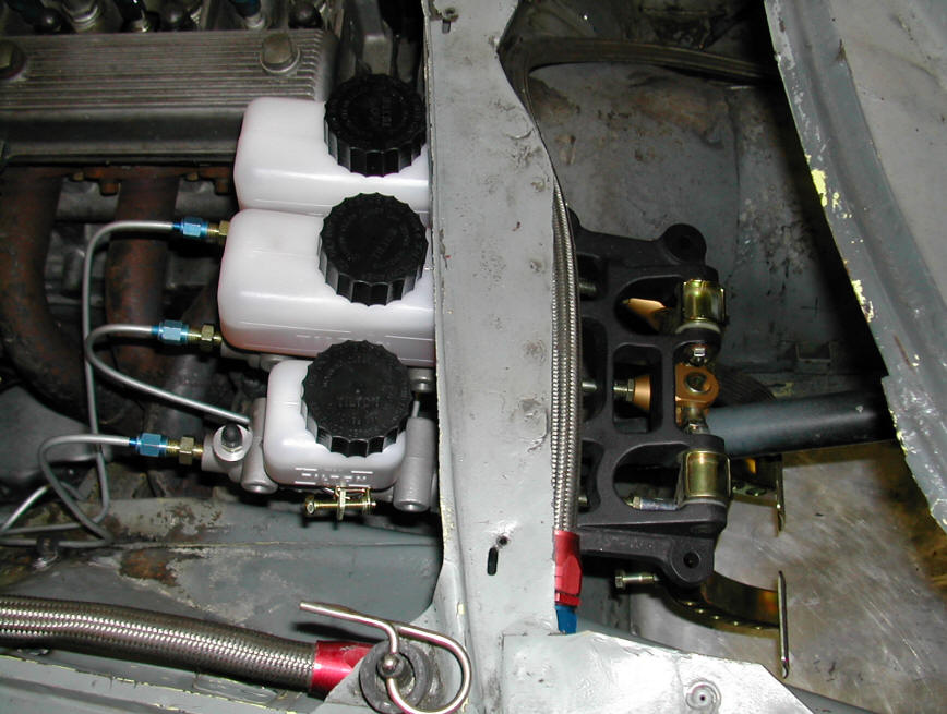
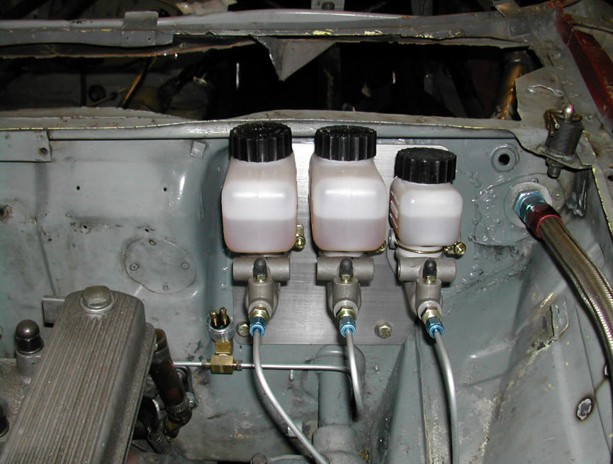
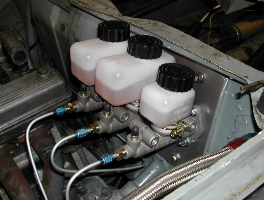
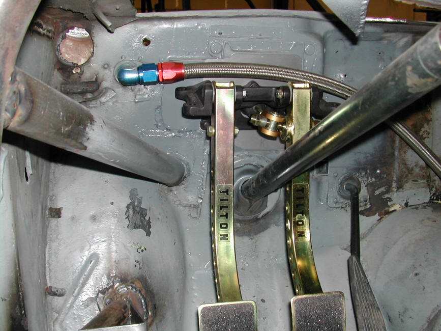
Typical MC/Bias bar/Pedal installation in a
fendered car - top mounted pedals (Click for full size images) [For more information about MOUNTING top pedals in a fendered car, see the instructions in the Brake Section]
|
||
|
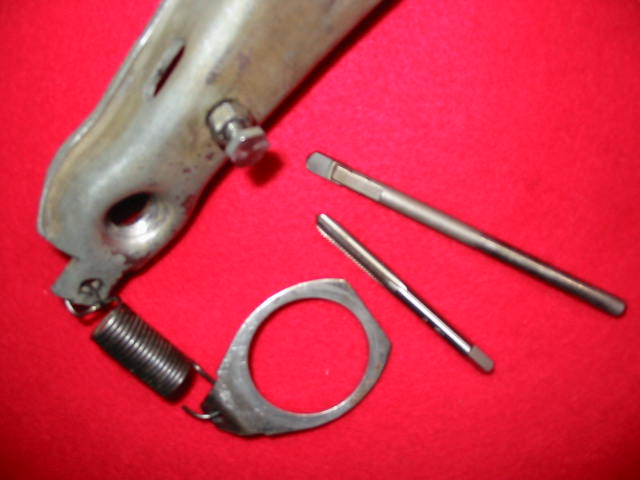
1.) Bend the first 1/2
inch of the tab end of the bracket to a 45 degree angle 3.) Remove the slave
cylinder from it's bore in the bell housing without removing the
hydraulic line if possible. (You may want to pop the piston out of
the slave cylinder and remove the spring that does not need to be
there.)
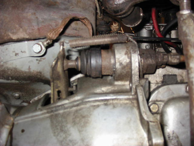
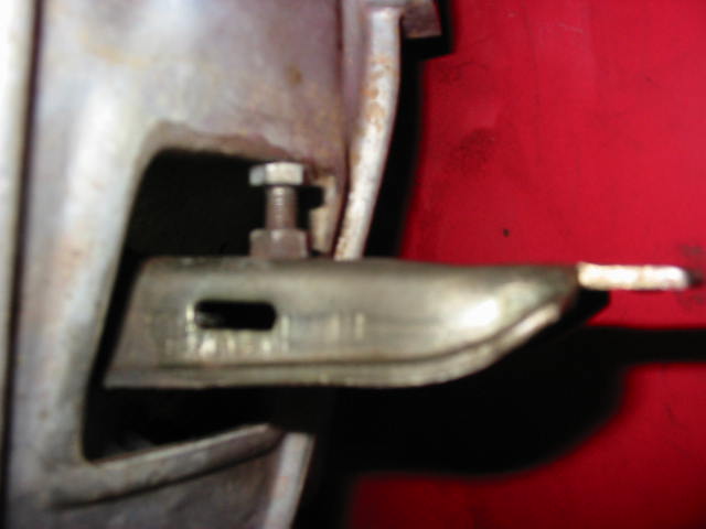
ADJUSTABLE FT STOP INSTALLATION INSTRUCTIONS FREE TRAVEL The consideration here is that the release bearing not ride on the pressure plate except during disengagement activity. With both Sachs and Tilton clutches, set the clearance at STOP to about .020". The arm ratio is 2:1 so the actual clearance at the release bearing is .040". The important consideration with a Tilton clutch is that the stroke, or total depression of the diaphragm spring be limited .700". Over-stroking even once may damage the clutch. All Alfas have a pedal stop adjustment. All of our Tilton pedal assemblies have this feature. Set the stop just beyond the point of release. 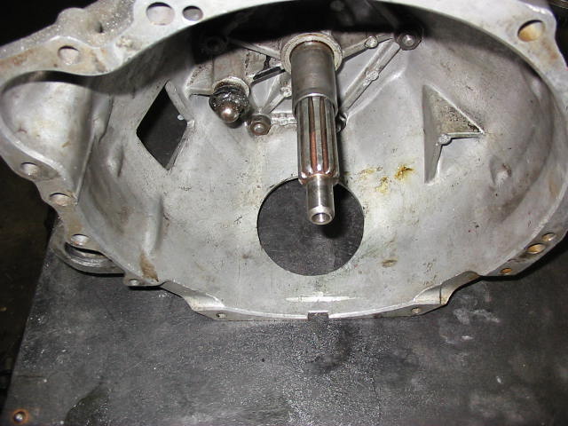 Interior of bellhousing showing the clutch pivot knob. |
||
|
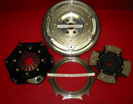
TESTIMONIAL .....7.25" TILTON RALLY CLUTCH SET UP Two years ago, this customer bought a complete 7.25" SM flywheel with Tilton Rally pressure plate, our sprung four puck disc and release bearing. This is our email exchange with Jerry A. Hi Paul, Quite happy with the 7.25 flywheel/sprung rally disk. Trying to figure where I am in the wear cycle...now measures about .290" or so, note the wear limit is .280, but don't know where it started. What is the thickness new? Thanks, Jerry A SM Reply: Our new rally discs start out at about .300" thickness. We use two different compounds to balance wear and smooth engagement. The hard compound is mounted on the flywheel side where most of the wear occurs. Great to hear it is working as anticipated. Paul, Wow!! If the disc started at .300 and I'm now at .290, I should have another 2 years to go! I'll be relining the disc in a couple years. It works, and I'm happy with it. Amazing the abuse this stuff will take with a few thousands wear. Not that I abuse stuff. Thanks, Jerry A.
|
||